Gfci Outlet Wiring Diagram
Gfci receptacle and switch same box electrical wiring home electrical wiring outlet wiring. Each component should be placed and connected with different parts in specific manner.
Leviton Gfci Receptacle Wiring Diagram Free Wiring Diagram

Connect the grounding wire (only if there is a grounding wire):
Gfci outlet wiring diagram. Each part should be placed and linked to other parts in particular way. The toggle switch in the combo switch outlet controls the first light bulb while the single way. In the first diagram the single way switch and light bulb is connected to the load terminal of gfci.
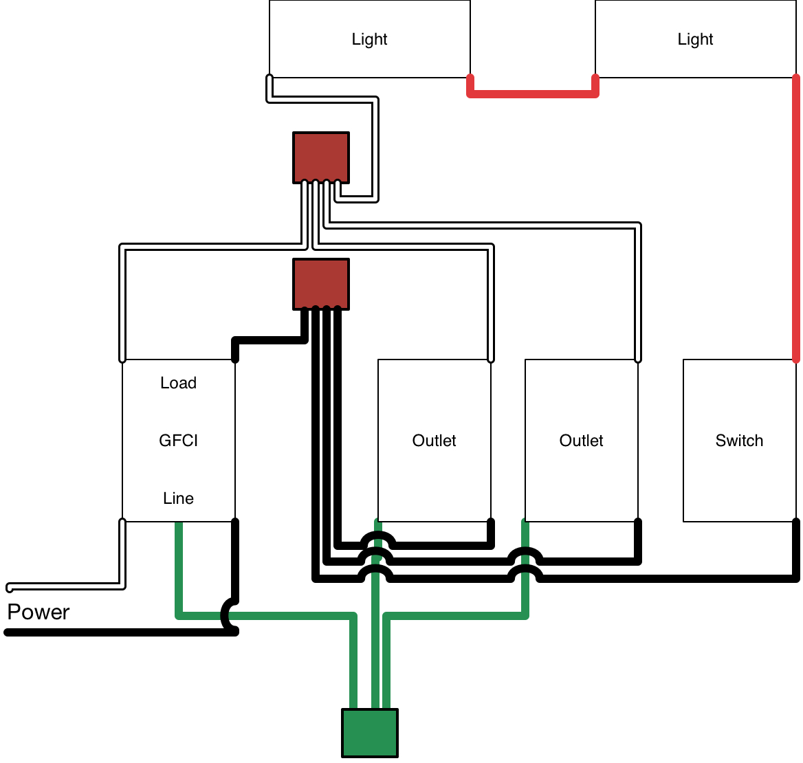
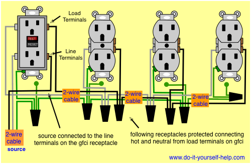
Illustrated guide for wiring a single gfci receptacle outlet typically used as bathroom gfi, kitchen gfi, outside gfi and garage gfi outlet. Wiring diagram also offers useful recommendations for tasks which may demand some added gear. Below mentioned wiring diagram shows a single gfci outlet connected with the multiple outlets.
You can wire a single gfci with multiple outlets using the 2 wires cables, multiple outlets, and gfci. Wiring a gfci outlet and a light switch. Gfci outlet wiring diagram house electrical wiring diagram.
8 per page 16 per page 24 per page. • the white wire connects to the gfci white lead. This book even consists of suggestions for additional provides that you could require in order to end your projects.
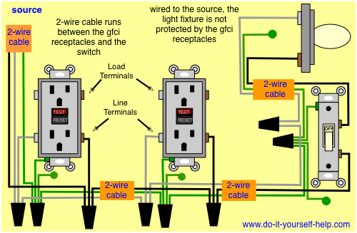
Power is connected to the gfci line side. This diagram illustrates wiring a gfci receptacle and light switch in the same outlet box a common arrangement in a bathroom with limited space. How to wire a single gfi outlet.
In this gfci outlet wiring and installation diagram, the combo (switch + outlet), spst (single way) switch and ordinary outlet is connected to the load side of gfci. Gfci outlet with switch wiring diagram how to install a gfci with 4 wires luxury wiring diagrams for a gfci outlet do. The three phase wiring for gfci or rcd rccb or rcbo wiring diagram shows the three lines l1 l2 and l3 and neutral has been connected as input to the rccb from main board followed by mcb ie.
Wiring a gfci outlet with diagrams pro tool reviews. Anko gfci outlet 20 amp ul listed led indicator tamper resistant weather receptacle indoor or outdoor use with decor wall plates and s online in vietnam b08n5hj337. Wiring a gfci receptacle is a little more complicated than hooking up a regular outlet but easily learned once explained.
Otherwise, the arrangement will not function as it should be. It contains directions and diagrams for various types of wiring techniques along with other products like lights, windows, and so on. Wiring a gfci outlet and a light switch.
Ground connection is not shown. Wiring diagram for a switched gfci outlet outlet wiring gfci wiring outlets plug a clock radio or light into the outlet. The wires attaching to the gfi outlet connect to the line side.
Leviton 20 amp 125 volt combo self test blank face gfci outlet white r98 gfrbf 0kw the. • for a box with no grounding terminal (diagram not shown): You can also learn about wiring gfci outlets in the following 7 steps.
Hot tub wiring diagrams use a gfci disconnect designed for 240v hot tubs 4 or 3 wire spa types. The gfci outlet protects electrical wiring and receptacles from overheating and possible fire, greatly minimizing the risk of shock injuries and fatal burns. Gfci wiring diagram with switch.
Detailed instructing by choosing installing and wiring a gfci outlet. Protected receptacle (s) will be connected to the gfci load side as shown below. *line and load terminal locations can differ between gfci receptacle brands.
Electrical panel wiring home electrical wiring electrical panel. Wiring diagrams for ground fault circuit interrupter receptacles gfci electrical wiring home electrical wiring. In the first diagram the single way switch and light bulb is.
You’ll have to use that single gfci as the source and then connecting the rest of the outlets using the same load and line terminals. It means, all the connected loads to the load terminals of gfci are protected. • the black wire connects to the gfci hot lead.
Outlets on same circuit diagram outlet wiring electrical wiring gfci. Wiring for a switch and gfci receptacle in the same box is also shown. In the gfci mainly two wires connect as also shown in a diagram the current flowing from the source and coming back are some due to current laws.
Connect the line cable's bare copper (or green) wire directly to the grounding lead on the gfci receptacle.
Gfci Outlet Wiring Diagram Wiring Diagram
Gfci Receptacle Wiring Diagram Free Wiring Diagram

Leviton Gfci Receptacle Wiring Diagram Free Wiring Diagram

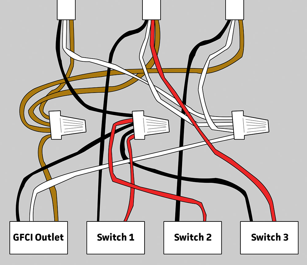
How To Wire To GFCI's With One Line? Electrical DIY Chatroom Home Improvement Forum

Electrical Engineering World GROUND FAULT CIRCUIT INTERRUPTER (gfci) Outlet Wiring Diagram
%2BOutlet%2BWiring%2BDiagram.jpg)
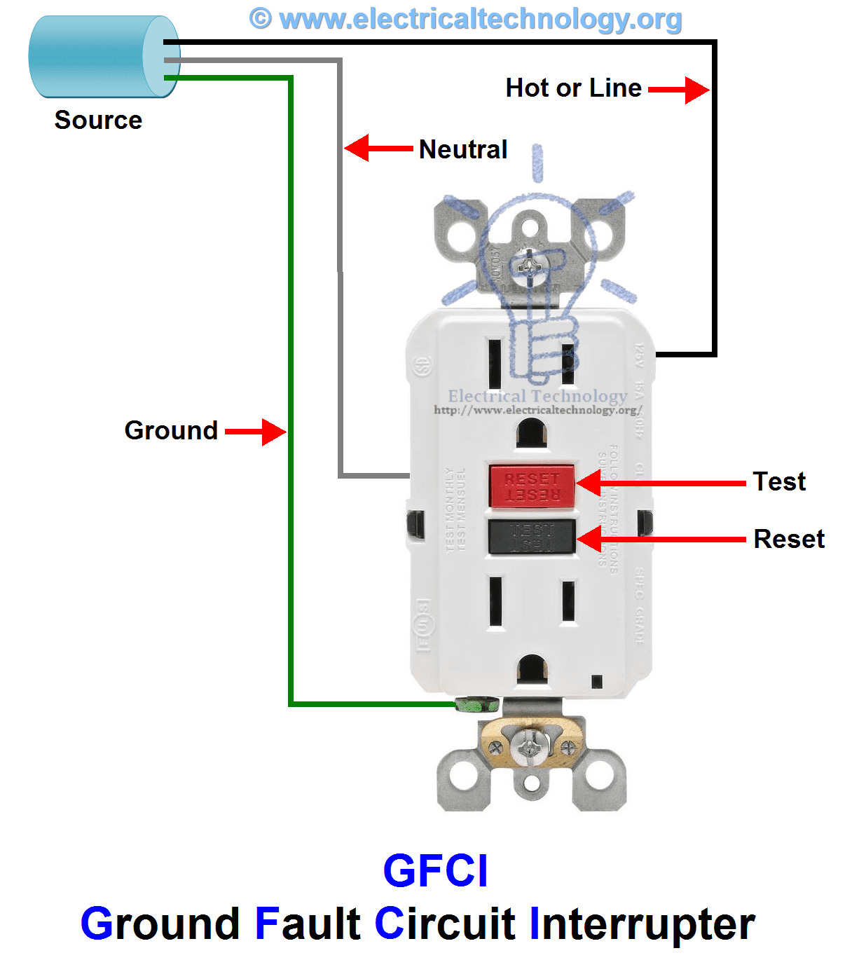
What is GFCI and How it Works? Ground Fault Circuit Interrupter
GFCI Outlet Wiring Diagram House Electrical Wiring Diagram

I have a gfci outlet in my kitchen that will not reset. I replaced the old gfi receptacle with a

Gfci Outlet With Switch Wiring Diagram Wiring Diagram

Leviton Gfci Receptacle Wiring Diagram Free Wiring Diagram

What is the wiring schematic of a GFCI? Quora
Leviton Gfci Receptacle Wiring Diagram Free Wiring Diagram

electrical How do I replace a GFCI receptacle in my bathroom Chuck Force outdoor crafts

How To Install And Troubleshoot Gfci Gfci Outlet With Switch Wiring Diagram Wiring Diagram
Wiring Diagrams for GFCI Outlets
GFCI Outlet Wiring Diagram House Electrical Wiring Diagram

Ground Fault Receptacle Wiring Diagram Free Wiring Diagram

Wiring Diagrams for GFCI Outlets
Gfci Outlet with Switch Wiring Diagram Free Wiring Diagram
