Variable Frequency Drive Wiring Diagram
Otherwise, there is a danger of fire. October 5, 2020 at 6:02 pm.
single phase VFD circuit using full bridge driver Electronic schematics, Circuit, Circuit projects

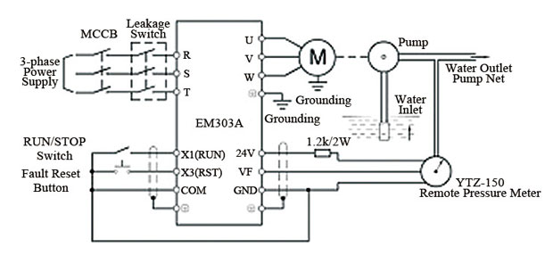
1 the vfd s three phase ac input terminals r l1 s l2 t l3 the power line s input terminals connect to 3 phase ac power through line protection or leakage protection breaker it does not need to consider the connection of phase sequence.
Variable frequency drive wiring diagram. Enclosure fan2 on 25hp and larger at 480v. Wiring and parameter setting of variable frequency drives. Abb vfd control wiring diagram.
Ts1, enclosure fan1 standard on all nema 3r panels. The vfd main circuit terminals shown as below figure. Then as per vfd logic if dl 1(digital logic) goes high vfd start to feed the output voltage, motor start rotating.
Connect or do wiring as per vfd side drawing, you take +24 v from the vfd pcb directly. Vfd is the abbreviation for variable frequency drive, also called variable speed drives and inverters. Abb acs550 ac variable frequency drive ::
9000x af drives 9000x af drives mn04001004e—may 2011 www.eaton.com i disclaimer of warranties and limitation of liability the information, recommendations, descriptions, and safety notations in this document are If customer safety interlock is used, remove j1. Please use screw drivers with appointed moment of force to
Use the following chart to interpret the type code found on the and control wiring. The acs adjustable speed ac drive should only be installed by a power circuit terminals u1, v1, w1 and u2, v2, w2 and, depending on the following diagram shows the terminal layout for frame size r3, which,. The drawing for vfd start stop wiring diagram from panel vfds are called as variable frequency drive or variable voltage variable frequency drive.
Vfd start stop wiring diagram: Simply put, they are motor controllers that regulate the frequency and voltage served to the. The vfds showed in the video are the d720s 230v single phase and the d720 230v three phase.
Controlled environment that is suitable for the selected enclosure. Collection of abb vfd wiring diagram. K1 no1, pb3, pb4, pb5 should be of potential free contact.
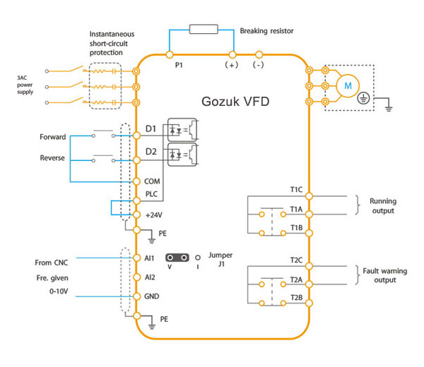
Fas/fhs without remote vfd keypad (1) the vfd's three phase ac input terminals (r/l1, s/l2, t/l3) the power line's input terminals connect to 3 phase ac power through line protection or leakage protection breaker, it does not need to consider the connection of phase sequence. In this lesson we will cover wiring diagrams of many different open loop applications.
Vfd start stop wiring diagram. 1 — ach550 variable frequency drive (vfd) fig. Acs550 nema 1 r1 through r6 frame size;
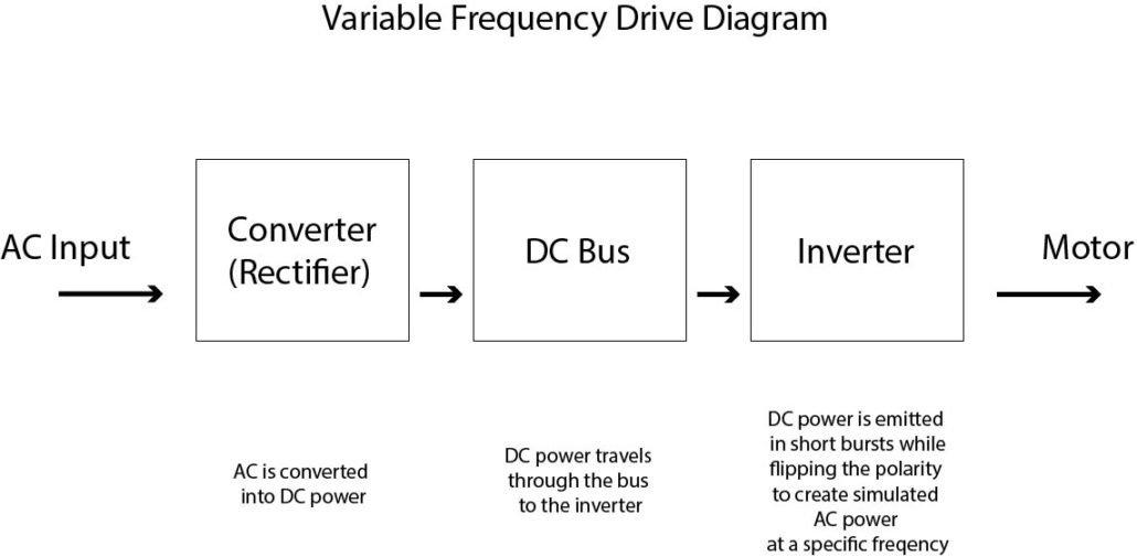
A variable frequency drive (vfd) is a type of motor controller that drives an electric motor by varying the frequency and voltage supplied to the electric motor. Frame 5, 2 contactor wiring diagram m34225 all panels shipped with vfd default programming parameters. The post discusses a single phase variable frequency drive circuit or a vfd circuit for controlling ac motor sped without affecting their operational specifications.
Abb acs550 ac variable frequency drive :: Every electronic enthusiast has come across the term vfd. Vfd circuit diagrams, types, and how to build one.
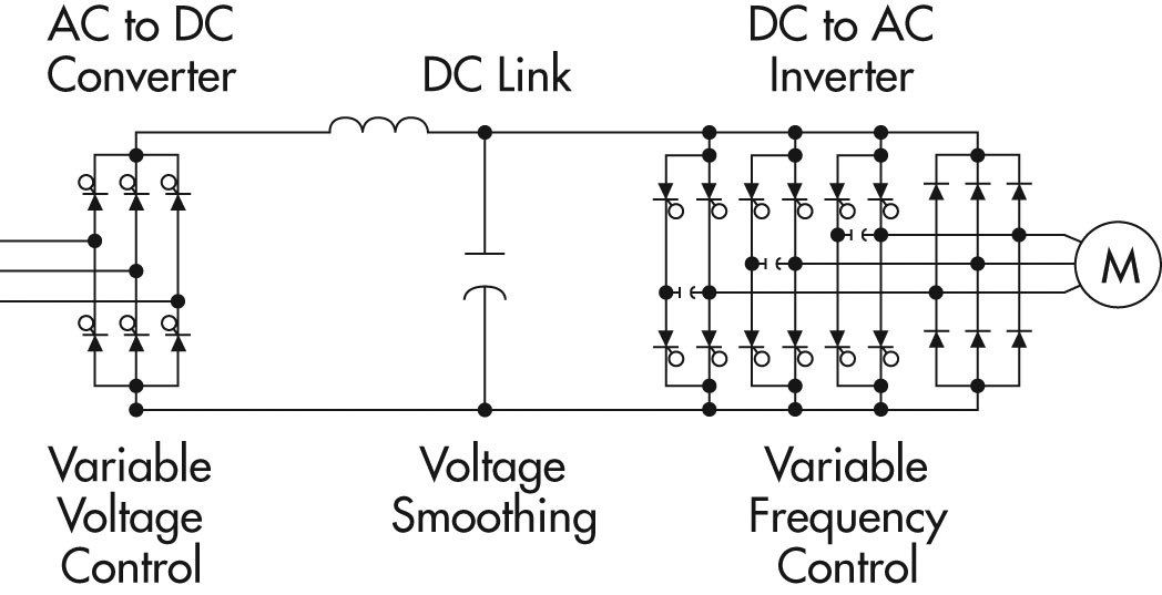
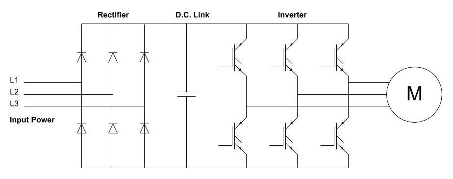
The three major sections of the controller are as follows: This includes wiring diagrams as well as parameters which we will be setting up shortly. Vfd wiring diagram how do.
A variable frequency drive regulates the speed and operation of an electric motors. On abb vfd control wiring diagram. Gk3000 series variable frequency drive (vfd) adopts speed sensorless vector control technology to offer excellent control performance, enhances operation reliability and environment adaptability.
The block diagram below shows a typical vfd installation. Abb acs550 ac variable frequency drive :: Control and power wiring diagrams.
Its primary use is to manage the speed of an ac motor. After applying the dc bus voltage across the igbts without the motor connected adjust the pwm 1k preset until the voltage across the rails become equal to the intended motor voltage specs. 480v ratings (pricing) abb acs550 ac variable frequency drive ::
The control circuit is separate from the motor circuit. When you press the on push k1 contactor will hold and k1 no1 become nc. Acs550 nema 12 r1 through r6 frame size;
Learn the basic wiring of variable frequency drives vfd with our electrician steve quist. Learn the basic wiring of variable frequency drives vfd with our electrician steve quist. Set dip switches as needed.
Layout monster vfd wiring diagrams diagram showing power in instructions add ons plc hmi and motor circuit 3 phase induction using variable sd control frequency drive for constant skills hands output board spindle start stop. With the use of the vfd not only saves energy but also saves the life of motors by providing a soft start and advanced process control Allen bradley powerflex vfd 700 to 750 753 drive 525 setup programming 40 ac drives parameter input and run off 110 for configuration low voltage rockwell automation modernization part iii 1305 adjule frequency 30 hp series not seeing digital inputs manual ppt 4m quick start blog ced.
Without any knowledge of frequency converters you will be able to draw a wiring diagram, connect and. A simplified vfd working principle diagram is shown in below. The ach is an variable frequency ac drive designed specifically for the hvac market that achieves control circuit connection diagram for each macro.
Allen bradley powerflex 525 ac drives ppt online. Danfoss vfd control wiring diagram.
Vfd Wiring Diagram
Single Phase Variable Frequency Drive VFD Circuit Circuit Diagram Centre

Variable Frequency Drive for Constant Pressure Water Supply
Basic Of Wiring A Vfd Inverter schematic and wiring diagram

Basics of Variable Frequency Drives Dreisilker Electric Motors
Principles of Operation AC VFD Drives
Phase Converter Wiring Diagram
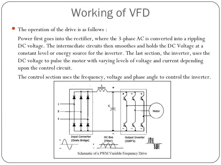
What is VFD, How it works? VFD working principle

Variable frequency drive in fans system Gozuk
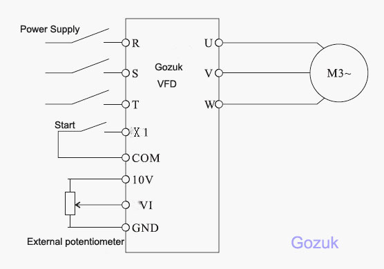
Fig 2 Variable frequency drive main circuit diagram EE Publishers

Variable Frequency Drive
Electrical Standards Variable frequency drive Working principle and circuit diagram

The post explains a simple variable frequency drive or VFD circuit which can be used for driving

Variable Frequency Drive Digital Inputs
The post discusses a single phase variable frequency drive circuit or a VFD circuit for

460V Variable Frequency Drives
.png)
Variable Frequency Drive All you need to know! [Along with FAQs]
Variable Frequency Drive (VFD) How To It Running with Minimal Effort

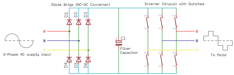
Internal Circuit of Variable Frequency Drive. Download Scientific Diagram